Im going to try to turn this post into a complete electrical and testing of electric components as im learning more about electrics myself .
if your interested in learning motorcycle electrical repairs i recommend this book its excellent, ive read it now 4 times over and over trying to master it. If you read this and absorb it you will be an expert on you bikes electrics , reading your manual is too complicated.
Cagiva Mito 125 Electrical Troubleshooting & Wiring Guide
Welcome to the ultimate digital resource for Cagiva Mito 125 wiring diagrams and electrical systems. Whether you are restoring a classic Mk1 7-speed, maintaining an Evo, or troubleshooting the modern SP525, having an accurate electrical map is essential for any DIY repair.
The Cagiva Mito’s Italian electrics are legendary, but they can be complex. This guide is designed to help you identify CDI pinouts, rectifier connections, and the CTS (Cagiva Tower System) power valve wiring without the guesswork.
Common Cagiva Mito Electrical Issues We Cover:
No Spark Issues: How to test your ignition coil, stator, and pickup coil values.
Charging Problems: Troubleshooting the regulator/rectifier and battery drain.
Power Valve Faults: Identifying the wiring for the CTS controller and servo motor.
Lighting & Indicators: Understanding the flasher relay and 12v loom distribution.
Technical Tip for Mito Owners:
Before diving into the diagrams below, always check your earth (ground) points. 90% of Mito electrical gremlins—including dim lights and intermittent cutting out—are caused by a corroded main earth strap on the frame or engine casing.
SP 525 wiring diagram
Cagiva Manual Wiring Diagram
--------------------------------------------------------------------------------------------------------
========================================================================
other wiring pictures ive found on internet over time that might be useful to you .
coil wiring
CDI
-----------------------------------------------------------------------------------------------------------
-----------------------------------------------------------------------------------------------------------
starter relay wiring
this EV2 has a 4 pin relay witha 5w multi plug with 5 wires, the centre pin clearly doesn't connect anywhere,
Relay pin markings:(moulded next to the spade connector)
S - Yellow
B - Yellow/Red line
L - Yellow/Black line
E - Blue
Spare centre wire - Red/Yellow line
Ev1 has a 5pin relay with a 5w multiplug with 5 wires.
A - Yellow
B - Yellow/Red line
C - Yellow/Black line
D - Blue
E - Yellow (the red could have worn off)this is the centre pin
top vertical- yellow/ blue (if this is the 12v switched from the starter button)
Bottom horizontal - yellow/red (the wire to the solenoid
Left vertical - Blue
Right vertical - Yellow
=========================================================================
instrument lights wiring pictures .
1 Main beam Dark Blue - White
2 Neutral Green/Black - Green/Yellow
3 Turn Black/Red - Light Blue
4 Oil Black/Green - Pink
5 Fuel Black/Green - Violet
====================================================================
r/h switch gear
========================================================
Black/Green 12v from ignition it goes to left switch gear, kill switch, horn power, PV controller & Flasher relay.
Brown 12v. Can't find it on the diagram above (but that for an earlier bike) But has black/green going to it the same as Black/green thats ignition feed 12v
Grey Is the horn circuit.
------------------------
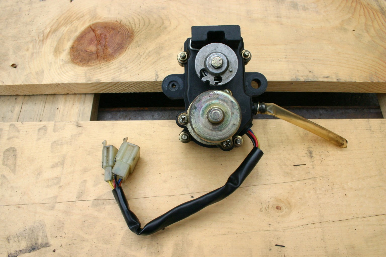
cagiva mito Power valve Cts electrics
cagiva mito Powervalve servo
Cagiva mito Cts Powervalve controller
====================================================================
Test battery at the negative and positive terminals
If you have a voltage meter you can do some basic tests.
When the engine has been off for at least 1-2 hours with ignition key turned off,
100% Charged 12.60 to 12.8v
75% Charged 12.4v
50% Charged 12.1v
25% Charged 11.9v
0% Charged less than 11.8v
=================================================
Must have electrical tool
12v circuit tester mines snap on but hard to
find in uk


.jpg)


.jpg)
.jpg)
.jpg)
.jpg)


No comments:
Post a Comment
No spam